Building a Digital Slot Machine: Dive into Sequential Circuits
In one of my CS courses, I studied digital electronics, including computer logic circuits and Boolean algebra. I had already read about how they work and had some basic understanding because I believed it would be useful for me as a developer. But when it came to creating my own task and designing a circuit for my idea, I quickly hit a wall, I lacked hands-on experience.
That’s when I asked myself: how do I improve this skill and truly understand the connections between components: circuits, functions, truth tables, K-maps, and registers? I decided to use Logisim and build my own 777 slot machine. After all, nothing teaches better than spending hours trying to build something with your own hands.
My idea was simple: assemble a circuit using built-in elements, design a custom decoder, connect it to 7-segment displays, and store intermediate results in registers. It’s a great way to explore how basic elements work, practice custom truth tables when designing a decoder, and see how memory works on the bit and register level.
Step-by-Step Slot Machine Design
Start Button (Clock Source)
I kept things simple here: I used a push button as the main trigger. When pressed, it sends a clock pulse into the system, activating the counters and starting the “spin” of the slot reels.
To broaden your understanding, note that instead of a button, you can use:
- a clock generator,
- flip-flops triggered by external events,
- sensors (e.g., light-sensitive),
- programmable timers,
- signals from a microcontroller or external device.
- This makes the system more automated and versatile.
Counters as Randomizers
To simulate spinning reels, I used three separate counters. Each one is a sequence of flip-flops wired together with logic gates.
A counter is essentially a chain of D flip-flops or JK flip-flops that change state with each clock pulse. For example, a 3-bit counter will cycle through values from 000 to 111, which represents 0–7 in decimal.
Typical logic elements used in counters include:
- D Flip-Flop: stores one bit of state, updated on clock edge;
- T Flip-Flop: toggles state on every clock cycle;
- AND, OR, NOT gates: used to manage counting, resets, and direction.
Decoders for Visual Output
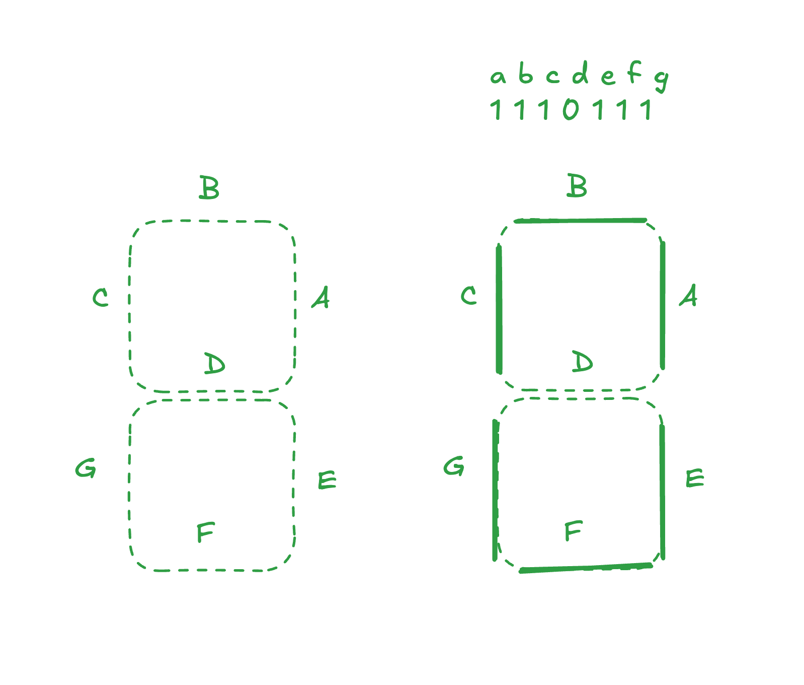
The binary outputs from the counters are fed into combinational decoders. These convert binary inputs (like 011) into signals that activate specific segments of a 7-segment display. This is a great opportunity to build your own decoder circuit and practice writing and understanding truth tables.
The goal is to translate each 3-bit combination into a set of output lines that turn on the correct segments for digits 0 through 7.
Truth Table (example for displaying digits 0–7):
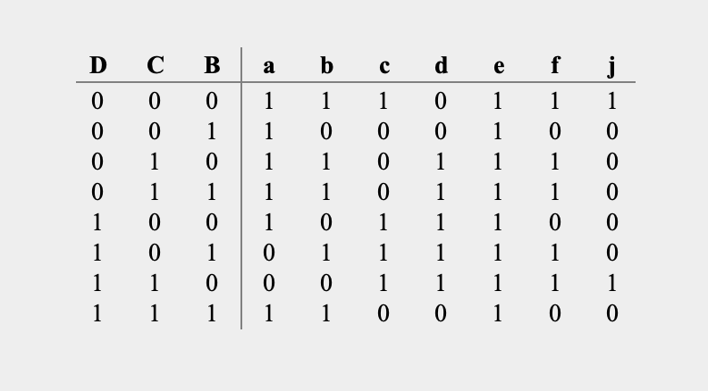
Each row corresponds to a 3-bit binary input, and segments a–g indicate which parts of the display should be active.
Karnaugh Map (K-map)
Using the truth table above, you could automatically generate a decoder using a tool — but it’s much more insightful to do it manually using Karnaugh maps.
Karnaugh maps are a visual method of minimizing logic expressions. Each cell in the K-map represents a row from the truth table and shows whether the output should be 1 (true) or 0 (false) for a given combination of inputs.
Let’s work through a concrete example for segment ‘a’ of our 7-segment display:
K-map for segment ‘a’:
     BC
A    00  01  11  10
0    1   1   1   1
1    1   0   1   0
Step-by-step minimization:
-
Find groups of 1s: Look for adjacent cells with 1s that can be grouped together in powers of 2 (1, 2, 4, 8 cells).
-
Group 1: The top row has four 1s (A=0, BC=00, 01, 11, 10)
- This group eliminates both variables B and C because they change but the output stays 1
- Simplified expression:
!A
-
Group 2: The bottom left corner (A=1, BC=00) and bottom middle (A=1, BC=11) can be grouped
- This group eliminates variable B because B changes (0→1) but output stays 1
- Simplified expression:
A & !C
-
Final expression for segment ‘a’:
!A | (A & !C)
This is especially important in manually implemented circuits (like in Logisim) because it:
- reduces the number of required logic elements;
- saves circuit space;
- improves readability and debugging;
and simplifies translation to microcontrollers or FPGAs.
OMG, Why I need to do that
This is a beginner-level project that’s incredibly helpful for understanding how digital logic systems function. It teaches you:
- how basic gates (AND, OR, NAND, NOT) work;
- the connection between truth tables and circuits;
- logic minimization using K-map;
and how to build complex systems from simple components.
If you want to dive deeper into digital electronics and logic gates, don’t hesitate to start with something fun and simple. Grab any circuit simulator and try building something of your own. It works at any skill level — and the learning payoff is huge.
To take the project further, you could add features like checking for winning combinations, storing spin history, or even building a simple betting interface. That’s what I might explore in the next article.
Usefull links
- Awesome project of creating 8-bit computer - https://eater.net/8bit
- K-maps online sandbox - https://www.boolean-algebra.com/kmap/